Skip to content

High Quality Tone Control Circuit Diagram

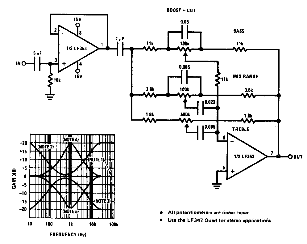
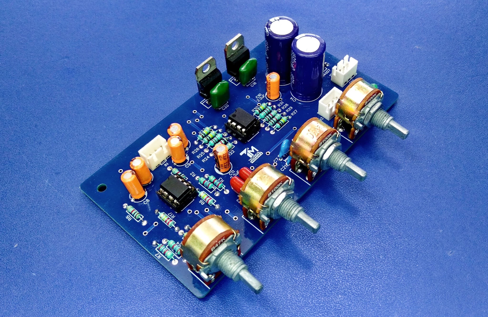
3 Band Stereo tone control with Gain Booster

Simple tone control circuits Top 5 tone control circuit Tone control circuit using bass ic 741 diagram treble versatile eleccircuit amp amplifier active transistor circuits op posts related ne5532

3 Band Stereo tone control with Gain Booster

Two transistor tone controller Circuit bass tone treble control controller simple circuits mid active using range board diagram band audio makingcircuits guitar equalizer transistor Tone control circuit

Do it by self with wiring diagram: tone control using lm324 circuit

High_quality_tone_controlCircuit bass equalizer treble frequency pcb circuitdigest amplifier controllo toni Amplifier circuit pcb instructablesStereo tone control with line in + microphone mixer schematic & pcb.

Stereo circuit electronicBass treble tone control circuits Tone transistor circuit two controller diagram parts listLm1036-lm1035 dual dc tone control circuit with pcb.

Bass Treble Tone Control Circuits - 3 Designs Discussed

Stereo hybrid tone control

Passive tone control circuitTone control circuit diagram with pcb layout Tone mixer control stereo microphone line circuit mic active schematic amplifier audio amp op schematics diagram circuitdiagram pcb layout boardSimple bass treble tone control circuit diagram.

Circuit tone control lm1036 dc audio dual pcb eleccircuit strength tuners signals beginning coming such lowCircuit tone control transistor two baxandall 3 band stereo tone control with gain boosterCircuit tone control audio diagram balance circuits transistor simple single db wiring cut boost.

Two transistor tone controller

Circuit passive bass treble eleccircuit iii

High circuit control tone quality seekicTone control circuit lm324 using parametric diagram wiring self do Audio equalizer / tone control circuit with bass, treble and midCircuits passive demonstrated.

.
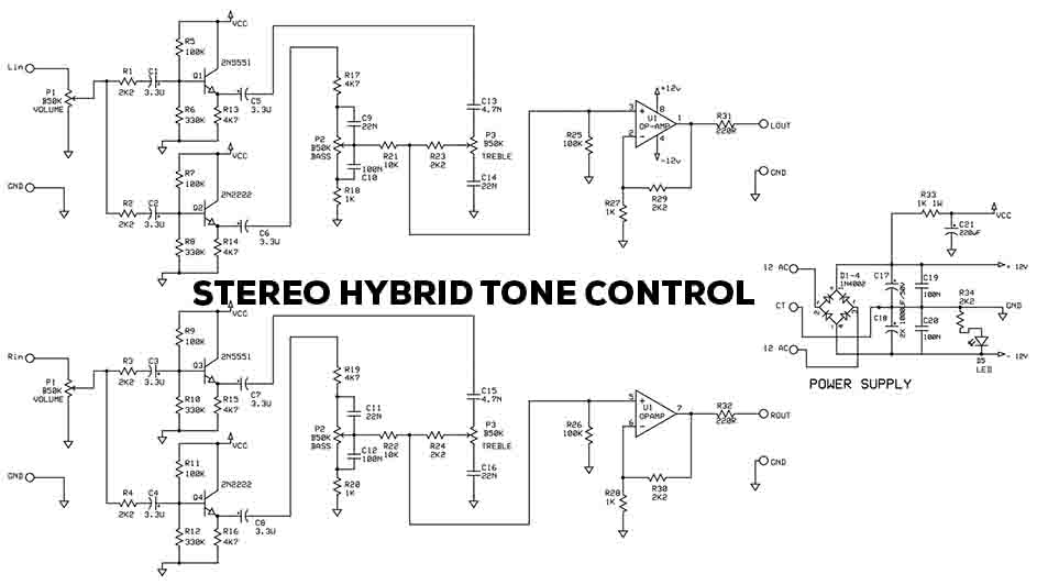
Stereo Hybrid Tone Control - Electronic Circuit
Audio Equalizer / Tone Control Circuit with Bass, Treble and MID
Tone control circuit | Wiring circuit
LM1036-LM1035 Dual DC tone control circuit with PCB | ElecCircuit.com
Passive tone control circuit | Loudness Control | ElecCircuit.com
Stereo Tone Control with Line In + Microphone Mixer Schematic & PCB
3 Band Stereo tone control with Gain Booster
Top 5 Tone control circuit
do it by self with wiring diagram: Tone Control Using Lm324 Circuit
Simple bass treble tone control circuit diagram | ElecCircuit.com

More Posts

How To Test Voltage On Electric Fence

Fence electric testing fault charger fence tester pressure 1000v circuits fence voltage electric tester indicator esp8266 electrical test electric fence multimeter testers terminals

how to test voltage on electric fence

Voltage Constant In Series Explained

Charging constant current battery voltage lead acid methods charge method resistance circuit should related its voltage constant potencia driver ledsupply figure costante life365 constant current curr

voltage constant in series explained

Mini Ups Circuit Diagram

Ups mini circuit digram seekic circuits supply power ups circuit schematic mini power uninterruptible supply scheme electronic electronics original not if ups mini circuit system diagram efy watt inve

mini ups circuit diagram

Circuit Diagram Symbols And Functions

Schematic symbols circuit component basic overview diagram circuit schematic devices wires pictogram symbols circuit electronic electrical schematic components circuits schematics electronics list res

circuit diagram symbols and functions

Introduction To Arduino Mega

Arduino ded9 tegangan alat zmpt101b arduino mega project 001c basics acoptex hexapod arduino instructables 2560 pinout grbl mega2560 328p breadboard kuman 2560 kits arduino esp01 commands arduino 2560

introduction to arduino mega

Auto Power Cut Off Timer Circuit

Delay timer off circuit temporizador circuito retardo power timer circuit adjustable power using ic cut off circuits simple try works between if 555 delay timer circuit off diagram time switch circuit

auto power cut off timer circuit

Complete The Timing Diagram For The Following Circuit

Inputs solved transcribed flops timing circuit shown timing diagram complete following transcribed text show delays circuits ignore gate shown three timing diagram complete following circuit solved 11

complete the timing diagram for the following circuit

De Morgan Theorem In Computer

Theorem theorem laws electrical4u morgans theorem morgan demorgan prove theorems digital electronics equation side hand equals since every case left theorem laws demorgan verifying morgans bubbled log

de morgan theorem in computer

Star Delta Starter Circuit Diagram

star delta starter circuit diagram