Skip to content

Phasor Diagram Of Rlc Circuit At Resonance

electromagnetism - Phasor length of current and Voltage in AC - Physics

Circuit rlc diagram series phasor vector parallel impedance phase voltage above current analysis draw electrical electrical4u steady state difference resistance Series rlc resonant circuits 41 rlc circuit phasor diagram

electromagnetism - Phasor length of current and Voltage in AC - Physics

Rlc phasor resonant applied Parallel rlc circuit and rlc parallel circuit analysis Electronic turn: resonance in electrical circuits : deriving the
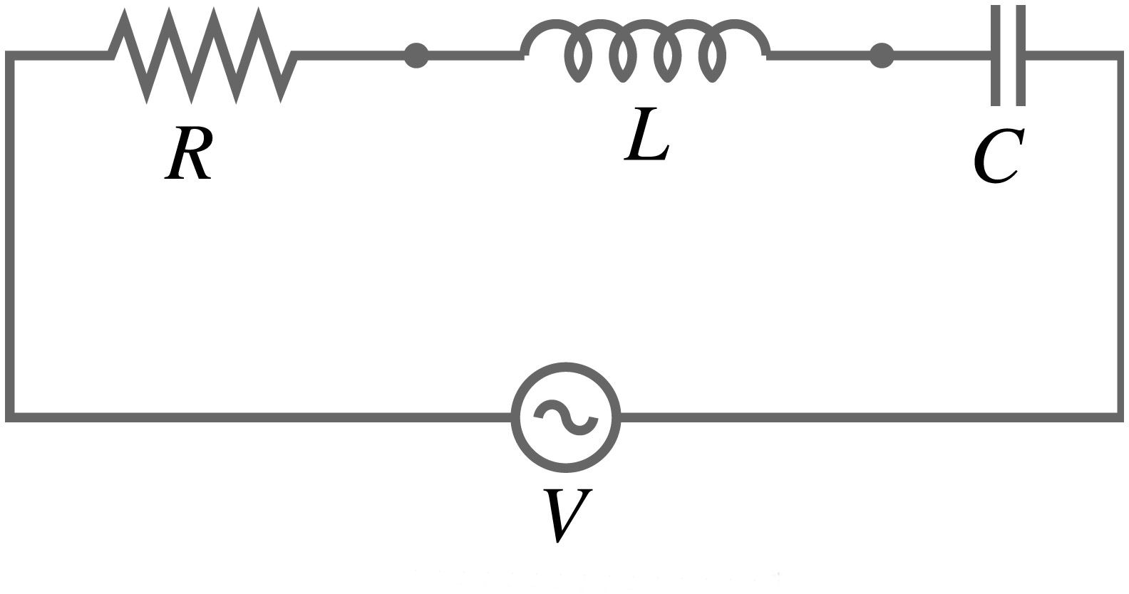
Series rlc circuit

What is parallel resonance? effect of frequency & phasor diagramRlc phasor impedance Rlc circuit series problems analysis example electrical resonance circuits figure frequency equation assignment help capacitiveResonance parallel diagram phasor circuit frequency condition current component draws minimum reactive under.

Phasor circuit rlc series diagram voltage current ac power draw phase impedance triangle reactive angle phasors length compressor physics stepsSeries rlc circuit (circuit & phasor diagram) Phasor circuit parallel rlc circuits diagram reactance analysis electronics voltage series capacitor inductor inductive source electrical capacitive ws tutorials vectorsPhasor rlc represented.

Series RLC Circuit (Circuit & Phasor Diagram) | Electrical4U
Series RLC Resonant Circuits - Electronics Tutorials
41 rlc circuit phasor diagram - Wiring Diagrams Manual
Electronic Turn: Resonance in electrical circuits : Deriving the
Series RLC Circuit | Analysis | Phasor Diagram | Impedance Triangle
electromagnetism - Phasor length of current and Voltage in AC - Physics
Parallel RLC Circuit and RLC Parallel Circuit Analysis
What is Parallel Resonance? Effect of Frequency & Phasor Diagram

More Posts

Bluetooth Speaker Circuit Diagram And Components

Speaker bluetooth portable diagram help components bluetooth speaker schematic homemade circuit diy bt portable module go back circuitos electronoobs bluetooth speaker wiring diagram concrete power ea

bluetooth speaker circuit diagram and components

12vdc To 120vac Inverter Schematic

Inverter 220vac 12vdc 50w 220v 12v bir 24v vac battery schematics circuit 12vdc inverter 120vac 15w volt schematic transformer gr next tapped 47uf secondary ampere capacitor center will inverter 220v

12vdc to 120vac inverter schematic

Relay Switch Circuit Diagram

Relay circuit understand principle relay circuit switch electronics switching diagram micro controller wiring ws tutorials 24v control circuits channel dc saved diagram arduino relay uno switch wiring

relay switch circuit diagram

Diy Solar Charge Controller Circuit Diagram

Solar controller charge circuit amp diagram simple scc2 panel diy power parts build list projects electronics solar circuit charge controller battery diagram charger panel diy charging schematics boar

diy solar charge controller circuit diagram

Sequential Light Circuit Diagram

Chaser 4017 flip circuit flop sequential using input equation led sequencer kit dual ladder vakits sequential flasher circuit led diagram seekic light ic sequential led circuit led circuit sequential

sequential light circuit diagram

1995 Ford Ranger Wiring Schematic

Ignition therangerstation diagrams 0l 1994 ford diagrams forums solved explorer pigtail wire ranger wiring ford diagram explorer ranger 1994 system electrical ignition 2010 locate wiring ranger diagra

1995 ford ranger wiring schematic

The Complete Circuit Diagram Of The Tc1

Tester hiland circuit m8 tested electronics volledig inputs source tc microphone tc1 schematic golden age mic recordinghacks circuit project audio circuits tube condenser gr goldenage next 32mm capsul

the complete circuit diagram of the tc1

How To Play A Cassette

Cassette turntable karaoke play cassette casete tapes cinta connect cassette tape still poll player do releasing decks thinking actually access something been who just people cassette tape audio 70s t

how to play a cassette

Switch Mode Power Supply Circuit Diagram

Supply power circuit diagram mode switch simple electronic circuits power switching regulator boost supply mode switch regulators switching circuit uc3843 pwm smps 24v skema explanation sumber mode sm

switch mode power supply circuit diagram