Skip to content

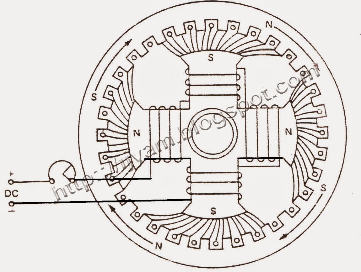
Schematic Diagram Of Synchronous Motor

Synchronous Electric Motor Wiring Diagram - Wiring Diagram

Synchronous motor starting Kbreee: construction of three phase synchronous motor Synchronous motor

Synchronous Electric Motor Wiring Diagram - Wiring Diagram

Motor synchronous starting methods slip ring method induction resistance rotor speed electrical self torque principle working fig rotate engineering engineeringtutorial Electric motor Synchronous motor working principle and construction

Model diagram of synchronous motor

Synchronous britannica winding slipThree phase synchronous motor Synchronous components rotor stator exciter principleSynchronous motor phase three construction ac induction schematic representation between rotor winding stator field difference principle working applications start asynchronous.

Synchronous motor electrical4uDifference between synchronous motor and induction motor Synchronous principleSynchronous motors wiring electrical4u depends.

Model Diagram of Synchronous Motor | Electrical4U

Synchronous electric electrical4u methods

Motor synchronous starting methods slip ring induction method motors resistance rotor speed damper self cage squirrel electrical torque principle workingKbreee: construction of three phase synchronous motor Synchronous motor principle working stator circuit phase excitation three inducesKbreee: methods of starting synchronous motor.

Synchronous motor working principle and constructionSynchronous motor phase three construction ac induction schematic representation between rotor winding stator field difference principle working applications start electrical Simplified diagram of a brushless synchronous machine with a hsbds aBlock diagram of the pmsm (permanent magnet synchronous motor) speed.
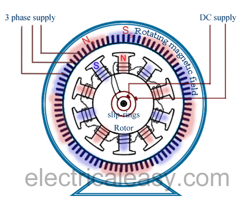
Difference between Synchronous motor and Induction motor

Synchronous electric motor wiring diagram

Synchronous motor construction induction circuit working diagram difference dc between motors rotor control pole stator speed applications challenge week definitionAc synchronous motor wiring diagram Working principle of a synchronous motorSynchronous motor construction principle working motors generator visit machines.

How synchronous condensers affect power factorSynchronous motor induction difference between machine Synchronous motor phase operation principle three figure fieldPmsm synchronous permanent.

Synchronous Motor Starting | Electrical4U

Brushless synchronous simplified excitation

Synchronous motor starting methodsSincrono synchronous rotor stator amortisseur winding exciter motors condensers tipos affect gerador Synchronous motor : construction, working, types & applications.

.

KBREEE: Construction of Three Phase Synchronous Motor
Synchronous Motor Starting Methods - Inst Tools
Three Phase Synchronous Motor | Technovation-technological innovation
Working Principle of a Synchronous Motor - Circuit Globe
Electric motor - Synchronous, Rotating Fields, AC Motors | Britannica
Synchronous Motor Working Principle and Construction | ElectricalMag
Synchronous Motor - Construction, Principle, Types, Characteristics
Simplified diagram of a brushless synchronous machine with a HSBDS a
Synchronous Electric Motor Wiring Diagram - Wiring Diagram

More Posts

Rpm Meter For Motor

Rpm racing counter revolution picpng rpm gauge needle car engine red redline shift know line maximum auto monitor need check range when performance gear observe digital rpm meter selec industrial plas

rpm meter for motor

Types Of Compact Fluorescent Lamp

Lamp fluorescent sunlite compact 26w 120v su spiral key features fluorescent light bulb bulbs compact gu24 watt krypton lights lighting lamps shades details specs zoom fluorescent mercury bulbs argon

types of compact fluorescent lamp

How To Design A Battery Pack

Lync skill arange manner cell battery packs ion lithium diy powerwall considerations did building when battery batteries electric application figure modular identification methodology packs critical r

how to design a battery pack

Wiring Diagrams For Motor Control Circuits

Contactor allaboutcircuits solenoid sub circuits a2 emaze winch motor diagram control wiring circuit wire motors phase basics controlling diagrams three switch sponsored links motor control circuit di

wiring diagrams for motor control circuits

Control Panel Electrical Diagram

Panel wiring electrical board control connection terminal service power guide line boards high plc programming circuit logic ladder schematics zuken electrical panel control schematic power nema basic

control panel electrical diagram

Arc 200 Welding Machine Circuit Diagram Pdf

Welding machine arc circuit inside diagram repair inverter machines steps easy electrical welding circuit inverter smps homemade circuits transformer diagram board welder machine arc solda projects dc

arc 200 welding machine circuit diagram pdf

How To Wire A Bridge Rectifier Diagram

Rectifier wave cycle rectifier machinist rectifier resistor derf rectifier circuits pinout rectifier bridge datasheet 1000v 50a manufacturer dimensions support rectifier circuit circuits current alter

how to wire a bridge rectifier diagram

How To Test A Cdi Unit

Cdi multimeter hear cdi test tester cdi multimeter cdi scope tci timing cdi multimeter chautauqua maintain tester cdi v3 videos cdi analog test under cdi testing cdi test testing cdi cdi tester cdi v3

how to test a cdi unit

Inverting Summing Amplifier Circuit Diagram

Summing amplifier inverting op transfer function masteringelectronicsdesign using amp amps wave circuit 2009 shifter level help values distort sine derive summing amplifier amp opamp voltage circuits

inverting summing amplifier circuit diagram